Lessons Learned from Meshing the McAlister Case
- Author:
Chris Bruner, Dept. 01515, Sandia National Laboratories
Introduction
The series of wind-tunnel tests described by McAlister & Takahashi [McAl1991] have become something of a canonical test case in the rotorcraft community. This is because the tests are well-documented and investigate both tip and aspect ratio effects, and because the symmetric wing section used is fairly representative of those typically found on rotorcraft.
This case also serves as a reasonably good test case for wind energy applications as there are measurements of the trailing tip vortex far downstream, up to 13 chords. This is important to understand the grid requirements of our unstructured approach to modeling a full-scale blade-resolved rotor and tower system.
Meshes
The meshes for this case are mixed structued/unstructured (hybrid) topologies. The mesh in the immediate vicinity of the wing uses a quad-dominant approach to produce mostly hexahedra in the wing boundary layer. This has most of the advantages of an unstructured triangular mesh in terms of ease of meshing and face isotropy in the interior, but has fewer elements for a comparable node count. A potential disadvantage is that there is no way to produce a mixed hex/tet mesh without the introduction of pyramid elements, which can cause convergence and accuracy problems. There is also a refined region around the tipe inside the wing box to ensure resolution of the formation of the wing tip vortex.
Further downstream, there is a fully structured hex mesh, expanding slightly and covering the path of the tip vortex downstream as measured in the experiment.
The balance of the test section mesh is unstructured tets (except as noted below), while another structured block is used upstream of the test section.
The meshes first produced used the Discontinuous Galerkin (DG) non-conformal interface between the hexahedral tip vortex mesh and the fully unstructured test section mesh. Due to the relative novelty of the DG approach and our lack of familiarity with its performance in Nalu-Wind, it was decided that a more conservative traditional, conformal interface between the blocks was preferable. Therefore, the tetrahedral test section block interfaces to the hexahedral tip vortex block and the upstream block using node-matched pyramid elements.
Notes on Geometry
The trailing edge geometry of the NACA0018 airfoil isn’t given in either the McAlister report nor in the original NACA publications describing it. Therefore, for ease of meshing, a rounded trailing edge was used.
In order to capture at least the gross blockage effects, the model support structure in the wind tunnel is modeled, and the tunnel walls are at the correct locations. However, in and effort to keep the mesh size low, the tunnel walls and the support are modeled as slip walls and not as viscous.
Most of the McAlister cases of interest were performed using a square wingtip. The initial mesh, however, uses the rounded tip described in McAlister. We will eventually produce a square tip mesh as this is both more interesting and has more-complete results.
Surface Mesh

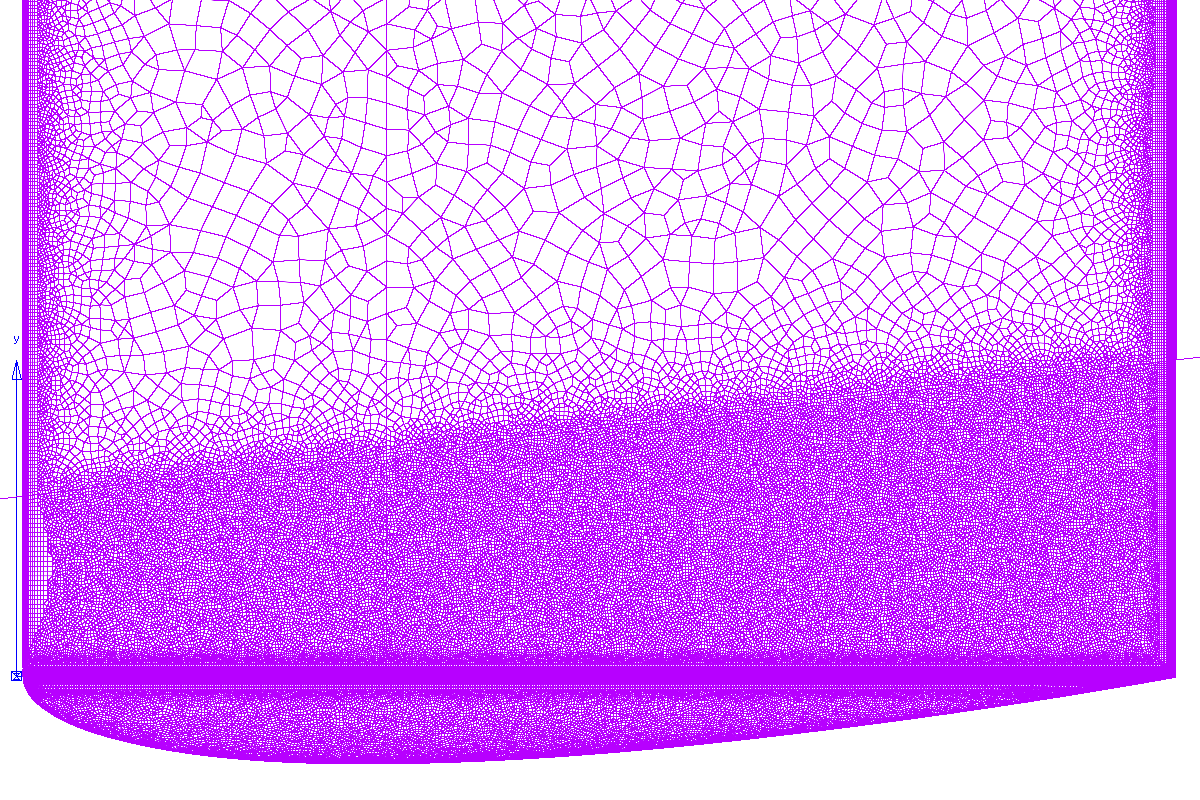
2 The surface mesh near the tip, as viewed from above.

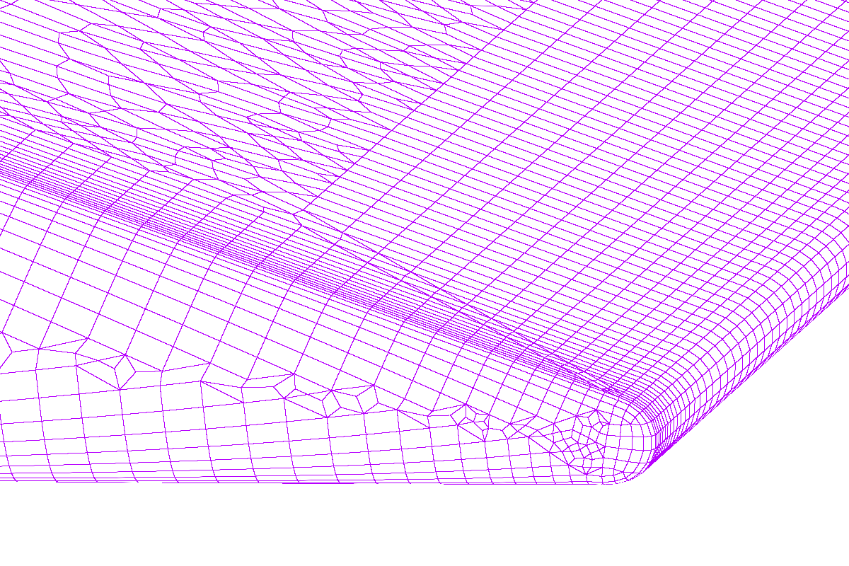
3 A close-up view of the tip and trailing edge, showing rounded tip and trailing edge and quad-dominant surface mesh.
Statistics of Current Mesh (grid07_conformal10.exo)
- Node count:
58M
- Element Count:
192M total, consisting of:
158M tets
2.5M pyramids
1.1M wedges
30M hexes
- Max. Centroid Skew:
0.866; 52 > 0.8
- Max. Included Angle:
177 degrees; 7 > 170 degrees
- Max. Volume Ratio:
22; 12 > 20
- Max. Aspect Ratio:
346
- Wall Spacing on Wing:
\(8.8 \times 10^{-5}\) m
- T-Rex Growth Rate:
1.2
- Full/Max Layers in Tip Block:
19/19 (limited to preserve quality)
- Full/Max Layers in Wing Block:
19/33
Lessons Learned
We need a lot of resolution to resolve and advect the tip vortex: on the order of 2–3mm edge length.
Due to the mathematics of physical space, small changes in the maximum edge length in a block lead to large changes in the final mesh size. For example, changing the maximum edge length from 0.0025m to 0.003m produces nearly a factor of 2 difference in the element count in the isotropic portion of the mesh: \((0.003/0.0025)^3 \approx 1.73\).
Heuristically, volume ratios should ideally be < 20. Slightly larger volume ratios are acceptable as long as there are no steep gradients passing through these elements.
Aspect ratios should be < 1000:1
Centroid skewness is a better measure than the other skewness metrics as it is more even across element topologies
equiangle skewness is also OK, but is stricter and can give misleadingly high readings for some tets
equivolume skewness is useless for tets
Centroid skewness should be < 0.8; however, skewness as high as the low 0.9s (usually associated with topology transitions) is acceptable as long as:
the skewed cells are far away from large gradients; and
there are no more than a handful.
General Pointwise Tips
Maximum aspect ratio for quads in domains should be \(\le\) 4 for good quality extrusions.
Maximum included angle should be \(\le\) 170 degrees. The usual exceptions for regions with small gradients should apply here, but there may be additional restrictions due to the elliptic nature of the incompressible flow equations.
It can be beneficial to push poor quality cells out of the boundary layer by increasing the minimum number of T-Rex layers.
One can set the maximum number of layers to prevent different numbers of layers in a block and its adjacent domains. This can eliminate some poor-quality tetrahedra.
References
McAlister, K. W. and R. K. Takahashi. NACA 0015 Wing Pressure and Trailing Vortex Measurements, NASA Technical Paper 3151. 1991.